
#
Component Diagram

This tutorial explains to you what a UML Component Diagram is. Here are the concepts explanation and an example.
A component has its behavior defined in terms of provided interfaces and required interfaces (potentially exposed via ports).
Component Diagram shows components, provided and required interfaces, ports, and relationships between them. This type of diagrams is used in Component-Based Development (CBD) to describe systems with Service-Oriented Architecture (SOA).
The Component Diagram does not describe the functionality of the system, but it describes the components used to make those functionalities.
Here is an example of Component Diagram:
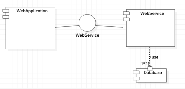
In Component Diagrams, the components provide a functionality. This functionality is called through a software. In my example, the Web Service is called by a Web Application. In order to know how to call that Web Service, you have to know how to call it. For this reason the Web Service must provide an Interface. An Interface tell you how you can access that component. This interface is used to create some Web Service functionalities as well. An interface is a class-like construct that contains only constants and abstract methods.
A Component might have other components included. Here is an example of Component Diagram:
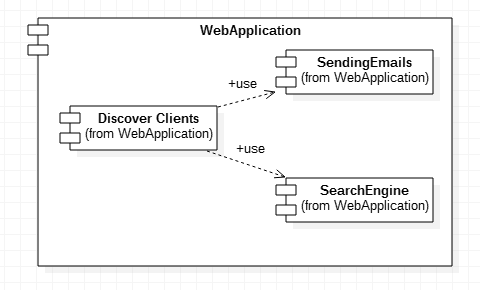
A component could be drawn differently, function of the UML version you use (in my example I used the "old fasion").