
#
Deployment Diagram

This tutorial explains to you what a UML Deployment Diagram is. Here are the concepts explanation and an example.
UML Deployment diagrams are used for describing the hardware components where software components are deployed. Deployment diagrams model the hardware used in system deployments, the system components deployed on that hardware and the associations between those components. In the Deployment Diagrams both hardware and software components are presented.
Here is an example:
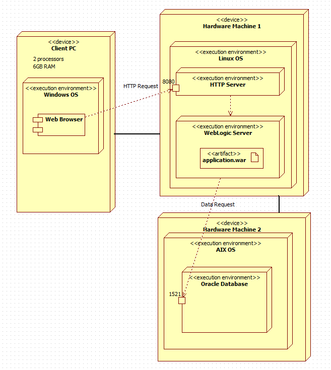
Into a UML Deployment Diagram we can have:
NodesA node in UML is a computational resource. There are two types of nodes:
device node = hardware devices, a physical computational resource with processing capability. Devices may be complex, and they may consist of other devices.
execution environments node = software containers (such as Operating Systems, Application Servers, JVM, Java containers, other servers). This is a node that offers an execution environment for specific types of components that are deployed on it in the form of deployable artifacts. Execution environments can be nested.
ArtifactsAn artifact is a file used or produces by a software (application, OS, etc). An artifact is symbolized by a rectangle with the name of that artifact and the word "artifact" enclosed by double arrows.ComponentA component is designed as a rectangle with two tabs that indicates a software element. A Web Browser is a software element.AssociationAn association is designed as a line that indicates a message or other type of communication between nodes.DependencyA dependency is designed as a dashed line that ends in an arrow, which indicates that one node or component is dependent on another.
Now you are ready to create a Deployment diagram in UML.